Addressing Operational Drift and Control Degradation
Introduction: The Fallacy of the Perpetual "Design Point"
When a centrifugal compressor skid is commissioned, its aerodynamic configuration, impeller stage selection, and surge protection protocols are strictly matched to a specified design basis—the rated operating point. Yet over a typical 15- to 20-year operational lifecycle, this initial design basis is often the very first assumption to break down. Depleting wellhead pressures, gas composition changes, plant debottlenecking, wide seasonal temperature swings, and internal physical degradation—such as worn labyrinth seals and aerodynamic fouling—inevitably drive the machine far from its original baseline.
In day-to-day plant operations, this departure is frequently met with localized workarounds: recycle valves to intentionally increase suction volume, or biasing inlet guide vanes (IGVs) or shaft speed to force the required discharge pressure. While these field adjustments may preserve short-term continuity, they mask a deeper, cumulative potential systemic risk.
Aerodynamic drift not only compromises inter-stage matching, but it also silently erodes the real margin of the anti-surge control system. When a severe transient occurs—most critically, an Emergency Shutdown (ESD)—a legacy control scheme operating on outdated performance assumptions can leave the machine dangerously vulnerable to deep surge and severe mechanical distress. For rotating equipment engineers, periodically conducting a closed-loop evaluation encompassing actual thermodynamics, transient gas dynamics, and rotor dynamic health is an essential operational requirement rather than an optional service.
1. Root-Cause Aerodynamics: How Operating Drift Disrupts Machine Equilibrium
Operating shifts are never merely a matter of moving instrumentation needles; they represent a fundamental departure in how energy is transferred throughout the gas path.
1) Gas Property Drift and Thermodynamic Restructuring
Changes in gas molecular weight (MW), compressibility factor (Z), and isentropic exponent (k) directly shift the acoustic velocity of the fluid and alter the required polytropic head (H_poly). At a fixed shaft speed, shifting fluid density forces the flow coefficient (φ) away from their aerodynamic optimums. The resulting flow incidence angles diverge from blade design vectors, triggering early boundary-layer separation, increased incidence losses, and a marked reduction in stable operating range.
2) Single-Shaft Architecture: The Compounding Risk of Interstage Mismatch
Most critical process units employ a single shaft compressor in a multistage inline/back-to-back architecture, mechanically locking all impellers to an identical rotational speed.
When suction conditions or gas density change, localized stage deviations do not remain isolated; they compound progressively through the casing:
"Surge Front / Choke Aft" (Under-capacity or Lighter Gas): When suction flow drops or the molecular weight falls, the initial stages suffer from flow starvation, sliding leftward toward surge. Because these early stages fail to generate design pressure rise and density accumulation, downstream stages receive gas that is less dense than intended. Consequently, actual volumetric throughput in the rear stages remains abnormally high, driving them toward aerodynamic stonewall (choke).
"Choke Front / Surge Aft" (Over-capacity or Heavier Gas): Conversely, if the gas becomes significantly heavier or mass flow increases, the inlet stages operate well into their high-flow, low-head region. The heavier gas experiences excessive compression and density buildup across the front end, starving the rear impellers of volumetric flow and driving the final stages prematurely across their surge threshold.
In either mechanism, the machine's usable operational envelope (turndown) is squeezed from both ends, leaving virtually no margin for dynamic swings.
3) The Cumulative Drag of Mechanical Deterioration
Internal mechanical degradation compounds these aerodynamic shifts. As balance piston labyrinths and interstage seals wear, internal leakage rates increase. This re-circulation not only slashes overall efficiency but also recirculates hot discharge gas back into intermediate suction passages, artificially elevating stage inlet temperatures. Coupled with blade surface deposition and fouling, the actual head-flow performance map deteriorates and shifts downward and to the left of the original factory acceptance curves.
2. The Control Disconnect: Why Conventional Surge Systems Become Compromised
Operating a compressor against drifted process conditions while relying on an outdated surge control philosophy creates severe vulnerability.
1) The Illusion of Static Surge Control Margins
In many aging installations, the Surge Control Line (SCL) configured within the controller remains identical to the baseline tuned during initial plant commissioning.
However, as internal clearances widen and gas conditions evolve, the true, physical Surge Limit Line (SLL) invariably drifts rightward toward higher volume flows. A nominal 10% or 15% safety margin configured in the control logic may physically be eroded down to low single digits. While the operator console indicates stable operation in the green zone, the impellers are actually hovering near fluid dynamic separation, where minor process perturbations can trigger full aerodynamic instability.
2) Emergency Shutdown (ESD): The Dynamic Risk of Deep Surge and Thrust Reversal
Static stability margins offer zero protection against the violent fluid and rotational deceleration that accompanies an unplanned trip. During an ESD event, driver torque drops immediately to zero, and the rotating assembly rapidly decelerates against the aerodynamic drag and system backpressure.
In systems designed without dynamic simulation verification, system parameters frequently fail to coordinate during this critical shutdown window:
Recycle Valve Latency: Instrument pre-stroke delay (solenoid and positioner reaction times) combined with physical valve stroking travel time.
Piping Capacitance: The expansion and pressure wave propagation time required to relieve large volume discharge headers (plenum capacity).
If the anti-surge valve cannot relieve system pressure before the compressor speed decelerates past its positive-flow pressure-generation capability, the machine is thrown into deep surge.
During deep surge, violent cyclic flow reversals take place in fractions of a second. The sudden collapse and inversion of stage differential pressures generate severe transient thrust reversals. The rotor assembly is repeatedly slammed between the active and inactive faces of the hydrodynamic thrust bearing, leading to active babbitt spalling, pad fatigue, or total bearing wiping.
3) Blind Spots in Incipient Fault Detection
Standard anti-surge algorithms rely almost exclusively on low-frequency thermodynamic process measurements: differential pressures (ΔP), static pressures, and temperature probes. These instruments are inherently damped by thermal inertia and transmitter scan rates. Sub-synchronous aerodynamic phenomena (such as rotating stall or early acoustic pulsations) manifest acoustically and mechanically long before gross pressure drops appear at the pipe wall. Without integrating real-time mechanical vibration metrics and fast dynamic logging into the machine protection architecture, the control system remains blind to the warning signs of surge until gross flow reversal is already underway.
3. Systematic Verification: A Four-Tiered Lifecycle Assessment Framework
To eliminate guesswork and safeguard plant assets, operating facilities should implement a disciplined four-part evaluation framework before committing to maintenance strategies or process re-rates:
| Engineering Dimension | Analytical Scope & Methodology | Actionable Engineering Outputs |
| 1. Thermodynamic Baseline & Mapping | • Real-gas Equation of State (EOS) modelling using site-sampled gas compositions (e.g., BWRS, PR, or REFPROP). | Quantifies true aerodynamic degradation, reveals internal parasitic losses, and defines the machine's actual working envelope. |
• Reconstruction of polytropic head ( ), pressure ratio, and efficiency vs. volumetric flow curves. ), pressure ratio, and efficiency vs. volumetric flow curves. |
| 2. Dynamic Gas Simulation & Transient Surge Analysis | • 1D spatial and temporal gas-dynamic transient modeling of the entire compression station layout. | Confirms whether the current recycle layout and valve trims prevent deep surge during trips; calculates peak transient thrust loads. |
| • Verification of valve pre-stroke delays, stroke times, and piping capacitance during ESD trajectories. |
| 3. Mechanical Integrity & Rotor dynamics | • Journal bearing load-eccentricity and temperature sensitivity evaluations under shifting density profiles. | Prevents fluid-induced sub-synchronous instability (oil whirl/whip), verifies thrust bearing margins, and ensures structural longevity. |
| • Re-calculation of net residual thrust loads across the balance piston under varied wear states. |
| • Rotor dynamic stability review, including cross-coupled stiffness at seals to meet API 617 log decrement requirements (δ>0.1). |
| 4. Driver & Station Infrastructure Interface | • Evaluation of driver rated continuous power, speed limits, and torque margins across maximum density extremes. | Identifies balance-of-plant bottlenecks to ensure auxiliary systems can support altered process conditions. |
| • Verification of nozzle Mach numbers, flange velocity limits, and allowable nozzle loads. |
4. Implementation Pathways: Engineering Strategies for Mitigating Drift
Once a comprehensive engineering assessment establishes the boundaries of the machine, facilities can deploy targeted, tiered interventions to restore reliability and efficiency:
Tier 1: Control Topology & Parameter Optimization (Software & Logic)
When aerodynamic components are structurally sound and process drift remains within allowable margins, protection can be restored digitally.
By inputting the recalibrated real-gas curves into the anti-surge controller, re-tuning derivative surge response gains, and adjusting pre-stroke margins, the unit's operating envelope is effectively re-established without mechanical modification or downtime.
Tier 2: Component-Level Modernization (Hardware Upgrades)
If the assessment highlights elevated thrust loading or rotor dynamic vulnerabilities stemming from higher gas densities, targeted internal retrofits provide high impact. Upgrading conventional labyrinth balance seals to fully machined honeycomb or pocket damper seals (PDS) dramatically diminishes destabilizing aerodynamic cross-coupling while adding direct positive damping to the rotor system. This stabilizes the rotor, lowers internal parasitic leakage, and balances net axial thrust across bearing pads.
Tier 3: Full Aerodynamic Bundle Revamp (Aero-Bundle Re-rate)
When operational demands deviate permanently from original casing capacities, attempting to operate with throttling valves results in unacceptable operational expenditures.
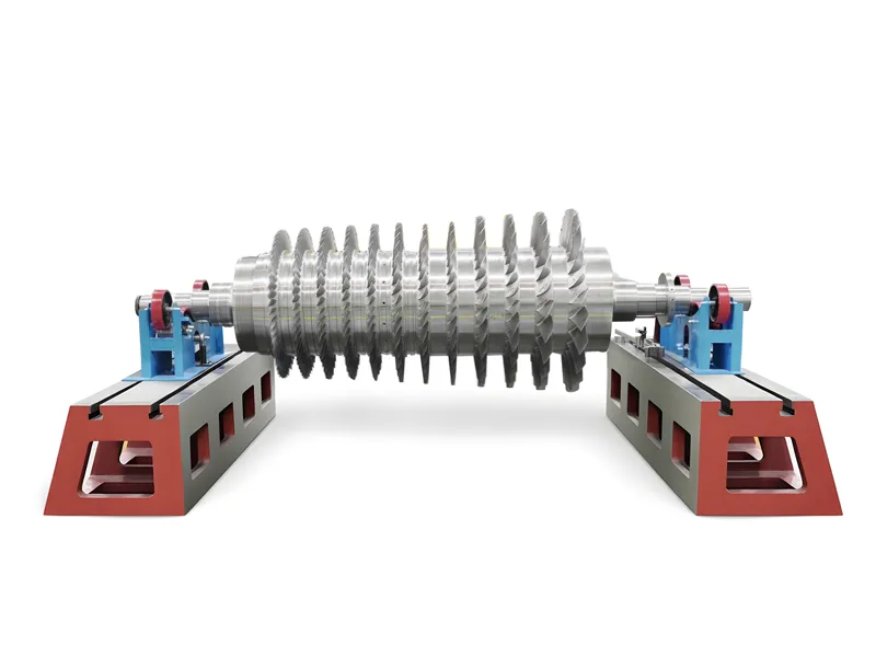
An aerodynamic bundle revamp
rotating assembly and stationary flow-path components (diaphragms, guide vanes, and balance components) with modern, custom 3D aerodynamic profiles engineered precisely for the new gas envelope—while preserving the existing outer casing, foundation footprints, nozzles, and driver infrastructure intact.
Engineering in Action: Offshore High-Pressure Gas Injection Revamp
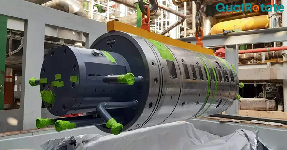
A clear example of this approach was demonstrated in an offshore project undertaken by QualRotate, involving three high-pressure natural gas centrifugal compressor trains in re-injection service under demanding platform space and weight constraints.
The application required re-wheeling the machines to handle an inlet pressure of 15.5 bara compressed to a discharge pressure of 154.5 bara—a demanding overall pressure ratio of nearly 10 across a single shaft. The process conditions introduced severe volumetric gas shrinkage in the latter stages and critical rotor dynamic stability considerations over an extended length-to-diameter rotor span.
By deploying comprehensive transient gas-dynamic simulations to re-engineer the station's anti-surge layout and valve timings and pairing this with a 10-stage custom aerodynamic bundle retrofit incorporating advanced damper seals, the engineering team resolved the risk of ESD-induced deep surge. The revamped trains achieved full aerodynamic compliance, enhanced stability, and high operational reliability—all while maintaining the original casings and nozzle orientations without structural modifications.
Conclusion: Regaining Predictability and Control
Keeping a centrifugal compressor running is not the same as operating it safely, efficiently, and predictably. In dynamic operating environments, relying on legacy control baselines and unverified protection margins exposes critical assets to avoidable failure.
By systematically assessing on-site thermodynamics, fast transient gas dynamics, and rotor dynamic health, plant operators gain the engineering clarity needed to make informed choices. Whether the resolution lies in software re-tuning, targeted component retrofits, or a full aerodynamic revamp, proactive lifecycle evaluation ensures critical turbomachinery remains reliable, efficient, and fully protected across its operational lifespan.

 English
 中文
中文