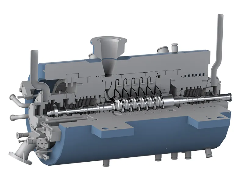
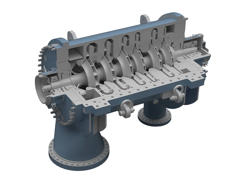
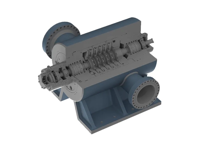
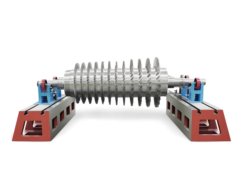
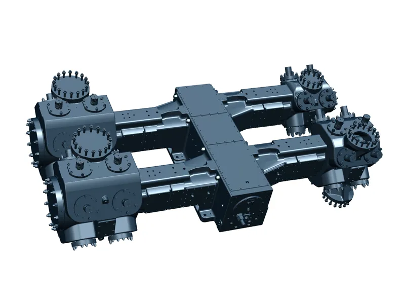
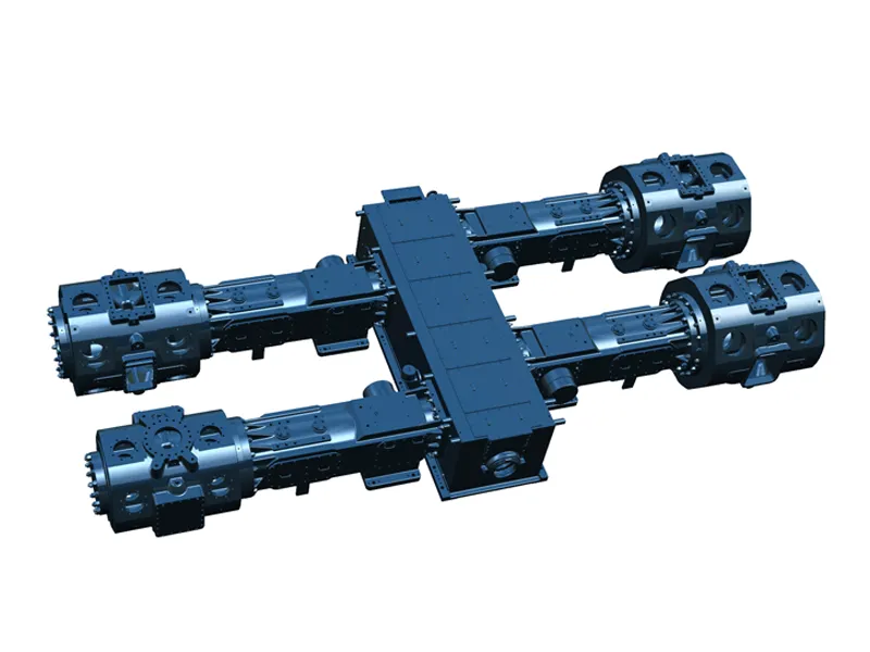
In centrifugal compressors, the shaft-end sealing area occupies a very special position. Inside the compressor is high-pressure process gas; outside it are the high-speed rotating shaft system, bearings, and lubrication system. This area must prevent uncontrolled leakage of process gas, while also avoiding long-term hard contact between the sealing faces. Dry gas seals are designed precisely to solve this seemingly contradictory problem.
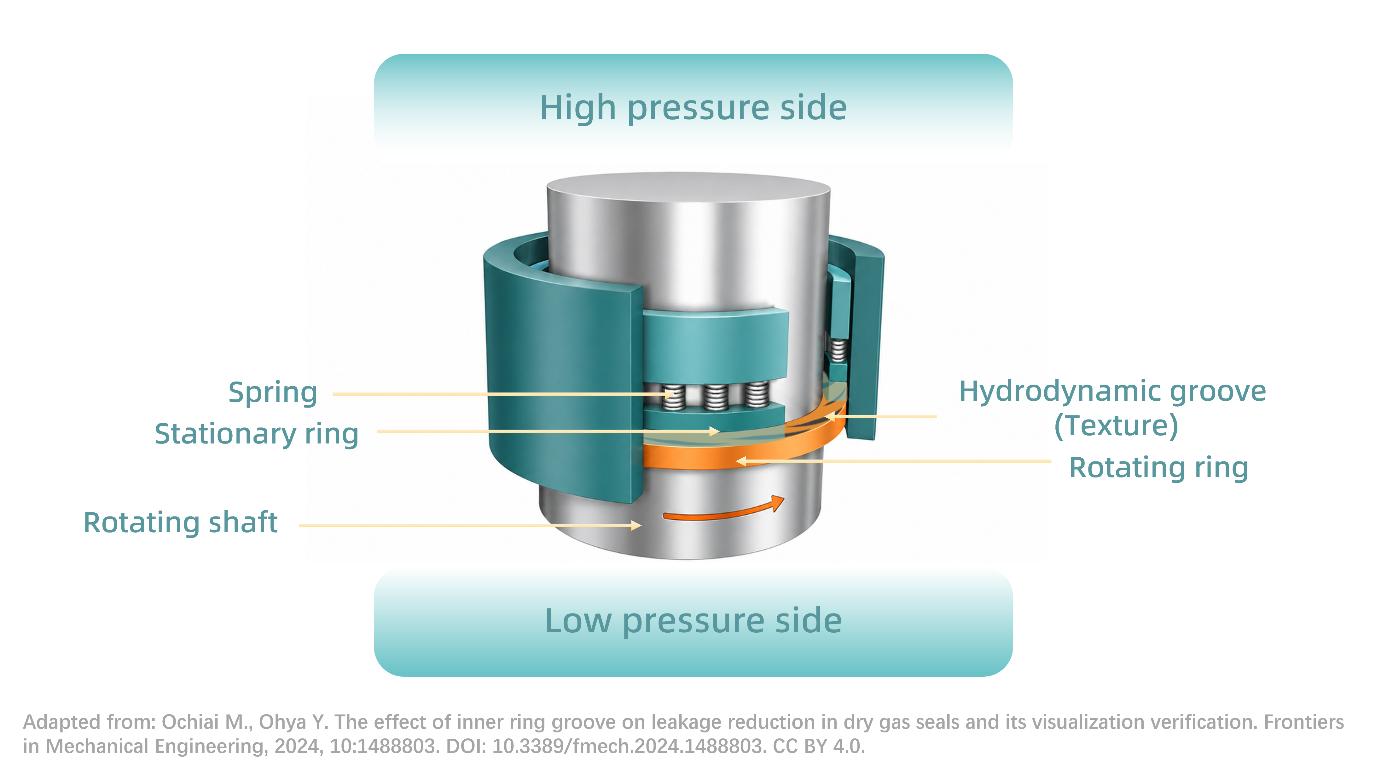
A dry gas seal does not rely on two faces being tightly pressed together, nor does it pursue absolute zero leakage. Its core principle is to form a micron-level gas film between the rotating ring and the stationary ring, keeping the faces in non-contact operation while allowing a small amount of gas to pass through in a controlled, stable, and monitorable manner.
In other words, the sealing performance of a dry gas seal comes from an extremely small clearance. This is the key to understanding dry gas seals: a micron-level gap forms the gas film, and controlled micro-leakage maintains the balance.
Micro-Leakage Is Part of How Dry Gas Seals Work
When first learning about dry gas seals, many people tend to understand “sealing” as completely blocking the gas. But for dry gas seals, a small amount of leakage does not mean failure. During normal operation, seal gas passes through the tiny clearance between the sealing faces and produces controlled leakage. This leakage is very small, but it is not an accidental leak point. It is part of what allows the dry gas seal to establish a gas film and maintain non-contact operation.
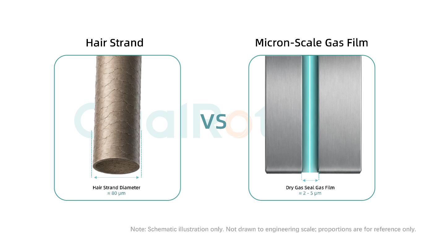
If the two faces are fully pressed together, friction, temperature rise, and wear will increase rapidly. If the clearance is too large, leakage will exceed the controllable range. What a dry gas seal truly needs to maintain is a dynamic state in which the faces are neither in hard contact nor too far apart. This state is extremely thin, usually only a few microns. For reference, a human hair is about 80 microns in diameter, while the gas film between dry gas seal faces is often only about 2-5 microns, roughly one-sixteenth to one-fortieth of the diameter of a hair. It is this nearly invisible gas film that determines whether the seal can operate stably over the long term.
From an owner’s site perspective, the key to judging the condition of a dry gas seal is not whether there is any leakage at all, but whether the leakage is stable, within the allowable design range, and whether it is accompanied by any abnormal changes in pressure, flow, vibration, axial displacement, or venting conditions. Stable micro-leakage is a normal operating state. Continuously increasing or suddenly fluctuating leakage is the operating signal that requires further investigation.
The Groove Pattern on the Face Determines How the Gas Film Forms
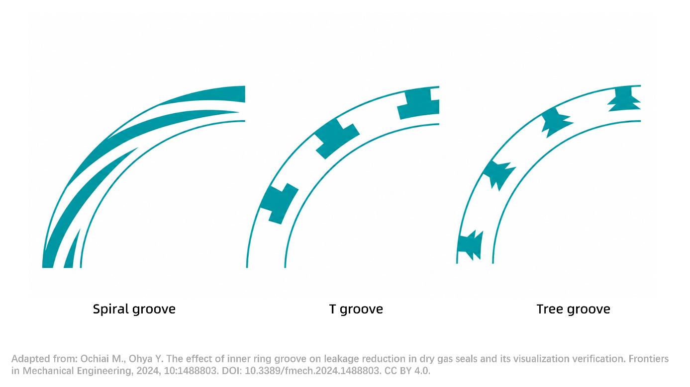
The fine patterns commonly seen on the faces of dry gas seals are not ordinary machining marks, nor are they decorative “patterns.” They are engineered hydrodynamic grooves on the sealing face, with common forms including unidirectional grooves and bidirectional grooves.
After the compressor starts, the rotating ring spins at high speed together with the shaft. Spiral grooves guide seal gas into the space between the rotating ring and the stationary ring. As the gas is compressed inside the grooves, hydrodynamic pressure is generated, gently lifting the two faces apart. This opening force is balanced against closing forces such as spring force and process gas pressure. Eventually, an extremely thin gas film is formed between the faces.
This gas film is the working foundation of a dry gas seal. If the gas film is too thin, the faces may come into contact, leading to wear, temperature rise, and face damage. If the gas film is too thick, leakage will increase and sealing performance will decline. If the gas film is unstable, leakage, vibration, alarms, and seal life will all be affected. Therefore, although spiral grooves may appear to be only a fine circular structure on the seal face, they actually involve gas dynamics, material pairing, face stiffness, operating pressure, rotational speed, thermal deformation, and many other factors.
Starting from a micron-level clearance, one can already see the engineering capability behind the entire compressor.
The Seal Gas System Determines Whether This Clearance Can Remain Stable
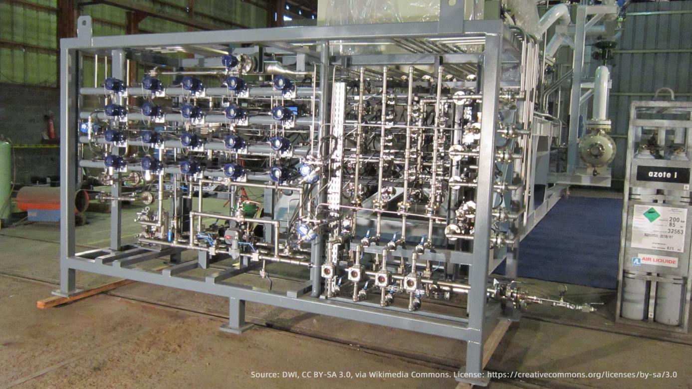
No matter how precise the dry gas seal itself is, it still requires a stable seal gas system to support it.
Seal gas must be clean and dry, with appropriate pressure and flow. If the seal gas contains particles, the sealing faces may be scratched. If the gas carries liquid, the gas film may be damaged. If the differential pressure is insufficient, process gas may flow back into the seal chamber. If the vent back pressure is abnormal, the leakage path may also be affected.
Separation gas is equally important. One side of the dry gas seal is close to the process medium, while the other side is close to the bearings and lubrication oil system. The function of separation gas is to prevent lube oil from migrating into the seal area. Once oil mist or liquid enters the sealing faces, the stability of the micron-level gas film may be compromised.
Therefore, dry gas seals cannot be evaluated by looking only at the seal cartridge itself. Seal gas source, filtration, pressure regulation, differential pressure control, venting, separation gas, and start-stop logic all affect the gas film between the faces. This is also why we say that compressor capability can be seen through a micron-level clearance.
On the surface, a dry gas seal controls shaft-end leakage. In reality, it connects the compressor’s process conditions, rotor condition, bearing system, lubrication system, seal gas system, and control and protection logic.
Repeated Seal Replacement Often Does Not Solve the Root Cause
During site maintenance, the most direct response to increased dry gas seal leakage is usually to replace the seal. But if only the seal cartridge is replaced without analyzing the cause of failure, the same problem may reappear in the next operating cycle.
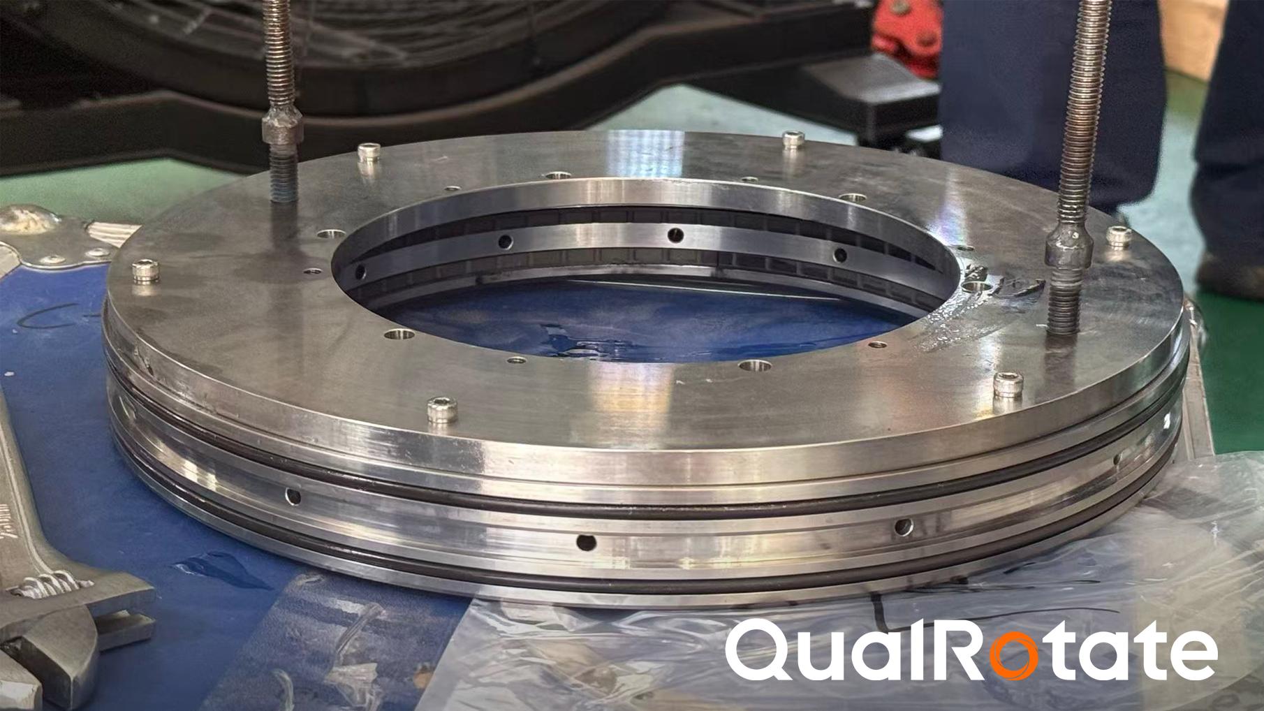
If seal gas contamination is not resolved, the new seal may still be affected by particles or droplets. If the supply differential pressure fluctuates over a long period, the gas film will still be difficult to stabilize. If rotor vibration or axial displacement is abnormal, the seal faces will still be subject to additional disturbance. If there are problems with the vent line, separation gas, or start-stop logic, the new seal will still return to the same risk environment.
Therefore, dry gas seal abnormalities should not be simply understood as “the seal is broken.” They are more like a concentrated reflection of the compressor’s overall operating condition at the shaft end.
For owners, the real value lies not only in installing a new seal, but in understanding why leakage increased, why the faces were damaged, whether the problem may recur, whether the seal gas system needs adjustment, and whether the alternative solution has been properly verified.
Seeing Compressor Capability Through a Micron-Level Clearance
The challenge of dry gas seals does not lie only in the precision component itself, but in enabling it to operate stably over the long term within a complex compressor system. A reliable dry gas seal solution requires comprehensive consideration of gas composition, pressure, temperature, rotational speed, shaft diameter, face groove pattern, material combination, seal chamber structure, rotor dynamics, bearing condition, lubrication oil system, seal gas system, and control and protection logic.
This is especially important in retrofit, localization replacement, and overhaul projects for existing compressors. Simply making the seal “fit” is far from enough. What matters more is understanding why the original seal failed, whether the existing seal gas system is still suitable for the current operating conditions, whether the compressor’s operating state has changed, and whether the new solution can operate stably over the long term under real boundary conditions.
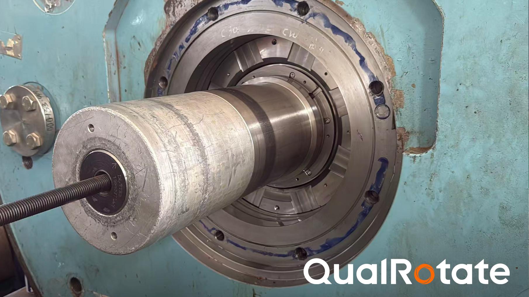
From a spiral groove on the seal face to pressure control in the seal gas system; from a micron-level gas film to overall vibration, axial displacement, and operating load, dry gas seals connect many system capabilities that may appear independent. This is why compressor capability can be seen through a single micron-level clearance.
As a complete compressor unit manufacturer, QualRotate always understands dry gas seals from the perspective of the whole machine. Based on actual compressor operating conditions, we coordinate process conditions, rotor systems, seal gas systems, and control logic to establish reasonable seal operating boundaries, achieve the best match between the dry gas seal and the compressor unit, and support long-term, safe, and stable operation.
From micron-level gas films to unit-level reliability, we welcome discussions on the practical challenges of compressor design, retrofit, and operation, and look forward to exploring more reliable complete-unit solutions together. [Contact Us]
(Images from public sources are used for technical illustration only. Please contact us for removal if any infringement occurs.)

 English
 中文
中文